|
|
The slider should be .020" taller than the depth of the T-slot so that
a portion will stick above, allowing clearance for the slider arm to move
without scraping the surface of the base. In my case, the slot worked
out to exactly .301" deep, so my slider should be .321" tall. Measuring
the current thickness of the brass piece, calculate the amount you need
to remove to make it .020" more than the depth of your T-slot. |
|
|
Once again, touch the tool to the part, lock the quill, move the table
to clear the tool, adjust and lock zero on the Z-axis dial. |
|
|
Raise the knee by the dimension you calculated and cut that amount off
the top of the brass piece. |
|
|
Now it's time to make the brass
piece into the T-shape that will fit the T-slots in the base. Using the edge finder, just touch the front
edge until the bottom section kicks over. Don't hesitate to repeat
the procedure as many times as necessary to be confident that you're getting
an accurate reading. |
|
|
Set the Y-axis DRO reading to zero. |
|
|
This time you'll be using the
1/2" end mill, and taking a precise cut
in from the front edge of the part. In order to do that, you'll need
to start with the end mill right at the front edge of the part. You
could simply lower the end mill and move the table Y-axis until the end
mill touches the part, and that would be pretty darn accurate if you're
careful. An even more accurate method is to use the edge finder. Keeping
in mind that the edge finder is .200" in diameter and the end mill
is .500, you can easily calculate how far over you have to move the table
once you find the edge with the edge finder. You can subtract half the
diameter of the edge finder from half the diameter of the end mill, or,
as I did here, you subtract the full diameter of the edge finder from the
full diameter of the end mill and divide by two. |
|
|
Either method produces the
same result, namely .150" Once
you get a good reading with the edge finder, move the table back away from
the edge finder by .150" |
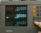 |
Set the Y-axis reading to zero. |
|
|
You now have the table set
so the bit will be aligned right at the edge of the part. Remove the edge finder and install the 1/2" end
mill. |
|
|
Subtract the final dimension
of the narrow portion of the slider from the current dimension, and divide
by two. If it comes out to an uneven
number of thousandths, round downward because you want a sliding fit with
no binding, so it's better to be just a taste undersize than oversize. |
|
|
Now to set the depth of the
cut for this important notch. This time
instead of working from the top, try working from the bottom of the part. Bring
the bit down to just touch the top of the parallel, which, of course, is
even with the bottom of the brass piece. |
|
|
Set zero on the knee dial. |
|
|
And lower the table by the
final dimension of the slider. When
lowering the table you have to be careful to count backward from zero because
you're going opposite the direction of the numbering. It's not that
difficult. Here, I've set my final dimension of .152" or .004
less than my final T-slot bottom height. The reading is 48 (100 minus
52) |
|
|
Move the Y-axis to .120 as calculated above, and lock the Y-axis |
|
|
Now, take a nice climb cut the length of the part. |
|
|
Take the brass out, turn it around and make a similar cut across the
other edge. |
|
|
With any luck, you now have
a nice sliding fit in the T-slots. If
the piece binds, check for burs and rough edges before trying to make any
adjustments in dimension. File all the corner edges, and you should
have a good fit. If you do need to take some material off, be quite
careful to make sure you can see where the piece binds before putting it
back on the mill to cut it. |
|
|
Measure the length of the slider. |
|
|
Make a nice black mark in the middle of the brass |
|
|
Set your caliper to half the length, and use it to scribe a nice sharp
line. |
|
|
You'll only have to be slightly
careful to cut this in half, leaving two pieces a bit over 1" long. |
|
|
Here's an easy way to make
both pieces exactly one inch long. Using
a single parallel that will allow about 3/4" to 7/8" of
clamping space above it, lower the quill until the 1/2" end mill just touches
the parallel. Lock the quill |
|
|
Set zero on the Z-axis dial. |
|
|
Lower the z-axis exactly one inch. On most mills, that will be ten full
revolutions. |
|
|
Place the two brass parts in
the vise, balancing their square cut ends on the parallel. All
vise jaws move slightly out of alignment when parts are clamped only
on one end, and you can take advantage of this by placing each piece
near the ends of the vise jaws. Then when the
vise is tightened, it will grip both pieces solidly. If you were
to clamp them next to each other it's very likely that one would be tight
and the other loose enough to shift position during the milling process. |
|
|
Mill the tops right off. |
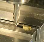 |
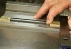
You'll have nice cut ends and accurate length. |
 |
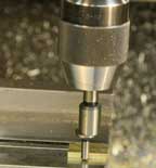
The next operation is to drill
and tap screw holes in the centers of the parts. This time you'll clamp both in place to keep
them solid, but you'll work only on one at a time. The idea is to
"index" the part right at the edge of the vise, so you can measure for
only one, but cut both exactly the same. Turning the pieces upside
down and gripping them by the small section you can slide one over to the
right, and position it exactly at the edge of the vise, using a parallel
as a guide. Hold the piece against the parallel as you tighten
the vise. Make sure you hold it down against the vise jaw top as you
do so. |
 |
You did file off all the burs
left by the previous operation, and you cleaned all the relevant surfaces,
didn't you? Right. Now it's
time to use the edge finder in a slightly different way to find the center
of the part. This happens to be my favorite method, finding both edges
rather than finding one and measuring the part. First, find the front
edge as before. |
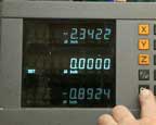 |
Then, set the Y-axis on zero. |
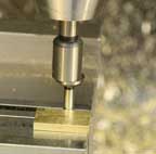 |
Now, find the back edge. |
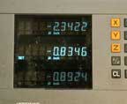 |
Note the Y-axis reading. |
 |
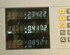
Divide that in half. Here I've
eliminated the "tenths" because that kind
of accuracy is beyond our scope. |
 |
Raise the quill to clear the edge finder, and move the Y-axis to the
calculated dimension. |
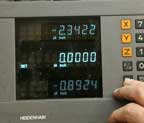 |
Set zero on the Y-axis of the
DRO. Now, anytime you want to return
to center, just go to "0." |
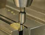 |
Now, repeat the process, this
time with the X-axis. Find the right
edge. |
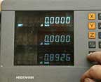 |
Set the DRO to zero on the X-axis. |
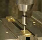 |
Find the left edge. |
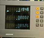 |
Note the X-axis reading |
 |
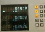
Divide by 2. |
 |
Raise the quill, move to the calculated dimension. |
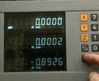 |
Set the X-axis to zero. Wow, now you can accurately find the center
of the part by simply moving the X and Y handles until you reach zero on
both DRO axis readings. AND, even better, you can do it again with
the other part as long as you index it against the side of the vise. Imagine
the time and effort you'd be saving if you had a hundred of these little
buggers to make. |
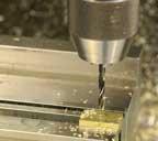 |
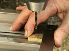
Put the drill chuck in the
spindle, and drill a hole on center (X and Y at zero, yes?) with
a #21 drill. |
 |
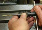
Quick, switch parts, index the new one against the vise jaw end, and
drill it the same way. |
 |
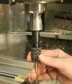
Load up the tap handle with
a 10-32 spiral point tap. Also known
as a "gun tap" because it "shoots" the chips ahead
as it cuts, this is the most efficient tap for threading holes that go
all the way through a piece. It's only natural to think that if you
have a nice straight hole, the tap will follow the hole and make nice straight
threads. Well,
sorry to say, it just doesn't work that way. In order to get straight
threads, you need to have a mechanical way to align the tap. Fortunately,
the milling machine can help. |
 |
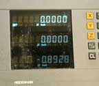
This is a technique you use with the machine turned OFF. First, stick
the end of the tap up into a collet of the appropriate size, and shove
the collet up into the quill, but don't tighten it there. |
 |
Then, return to zero to center the tap over the hole. |
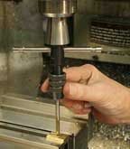 |
Stick the tap into the hole |
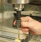 |
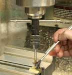
And, lower the quill almost
to the lowest it will go. Lock the
quill. |
 |
Apply a bit of tapping lubricant. |
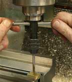 |
Proceed to tap the hole, with absolute assurance that the tap will be
guided straight and true. |
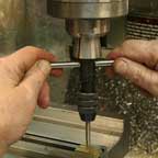 |
As you tap, the collet will
be drawn lower, but it will continue to do its job, nicely guiding the
process. |
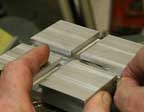 |
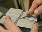
If you haven't already, go
ahead and use a small file to "break"
the corners of the slots and remove any leftover burs or roughness. |
 |
All corner edges will need a bit of attention. |
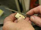 |
Same goes for the sliders. Stick the sliders in the slots, and
run them back and forth past the intersection. If they bump as they
go past the junction, give their corners a bit more relief. |
 |
The handle is aluminum, and, just like the other parts, it will need
to be trued up before use. |
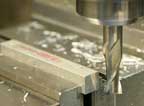 |
Trim the ends first. |
 |
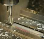
You'll want the handle to be
long enough to crank the mechanism nicely, but not so long that it gets
in the way of life in general. Something
between 3.5 and 4 inches seems good to me, and I settled on this length,
which is how my piece came out when I cleaned up the ends. |
 |
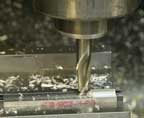
More milling, first the top
edge. The piece is supported on parallels,
of course, so everything will come out even. |
 |
Then, flipping it over, the bottom, and setting the depth of the cut
as in earlier processes, trimming it to the final dimension. |


