|
|
I chose .220, for a pleasing
look. And, it's a nice round number,
too. |
|
|
Same deal for the opposite
edges. First trimming for straightness,
then cutting to dimension. |
|
|
I like the idea of a 2x4, so I chose .440 for the width. |
|
|
Now, with the piece in the
vise, supported as usual with the parallels, you'll want to drill and
tap some holes. But you definitely do NOT
want to drill into the parallels. |
|
|
So, with the vise tightened, you can remove the parallels, and, if you're
at all reasonable about downward forces, the part will hold very well where
it is. |
|
|
Here we go again. Find the edge. But
this time, let's find center in a slightly different way. |
|
|
Set the Y-axis to zero. Raise
the quill to clear the tool. |
|
|
Move inboard half the
diameter of the edge finder. |
|
|
Set zero again. |
|
|
Now, move inboard half the
width of the part, which measures .440. This
way is easy, yes? |
|
|
Lock the Y-axis |
|
|
Now find the left edge of the part. |
|
|
Set the X-axis to zero. |
|
|
Raise quill, move to half the diameter of the edge finder. |
|
|
Set the X-axis to zero again |
|
|
Move the X-axis the same distance
as you moved the Y-axis. That way, you'll
have a center point near the end of the part. |
|
|
Set the X-axis to zero once again. Now, you can use this reference point
to locate a second hole. |
|
|
Drill through the part with
#11 drill. That's the standard clearance
drill for a 10-32 bolt. |
|
|
Position one of the sliders
in the center of the slot and the other right at the end of the opposing
slot. Measure the center-to-center distance
between the threaded holes. While there are methods for making very
accurate measurements, this job only requires "eyeball accuracy," so
you can simply position the points of the caliper about in the middle of
each hole. |
|
|
Move the mill table to the left by that same measurement, as read on
the X-axis of the DRO. |
|
|
Drill the second bolt clearance hole with the #11 drill. |
|
|
Find the right end of the part with the edge finder. |
|
|
Set zero on the X-axis |
|
|
Raise the quill, move toward the part by half the diameter of the edge
finder. |
|
|
Set zero again. |
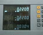 |
And, move the table to the right by .220, just as you did at the other
end. |
 |
Drill with the #21 drill, and thread the hole as you did when you threaded
the sliders, using the quill as a guide for the tap. |
 |
Making the little handle seems
like it would be a natural job for the lathe, and so it would. But, this is an exercise in using the mill,
so here's one approach that works pretty well. You'll start with a
short section of 3/8" diameter brass rod. Stand the piece up
on a parallel, and, using a second parallel as a guide, hold it vertically
as you bring the vise jaw up nice and tight. |
 |
Take a light cut off the top
with the 1/2" end mill. Turn the piece over,
clamp it the same way, and mill off a bit of the top once again. |
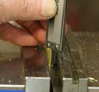 |
You can use the depth gauge
on the caliper to judge the length, and this time, instead of measuring
and calculating, just try "sneaking up" on the
measurement, taking a bit at a time. |
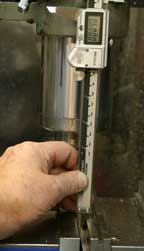 |
The precise length isn't critical,
but it's always a good idea to try for precision, so take it slow and
you should be able to come up very close to the ideal length of .600" |
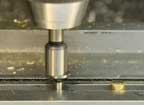 |
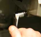
Now, to find the center of
that little piece to drill through it. First,
don't forget to take the parallel out from beneath the part so you don't
drill into that piece of precision measuring equipment. Rather than
finding the front edge of the part, use the edge finder to find the front
jaw of the vise on the inside. |
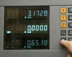 |
Set zero on the Y-axis of the DRO. |
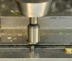 |
Find the inside edge of the back jaw of the vise. |
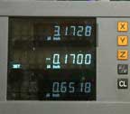 |
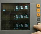
Note the reading on the Y-axis. |
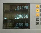 |
Move the table along the Y-axis,
and you'll be precisely centered
between the vise jaws, and consequently, centered on the part. |
 |
Lock the Y-axis. |
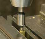 |
Now, since you are locked precisely on center, if you move the
table to the left, you'll touch the exact center of the circumference of
the brass rod. Find that edge. |
 |
Zero the X-axis of the DRO.
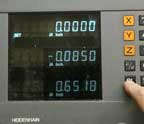
Find the right edge and note the reading. |
 |
Move the table until the X-axis reading is half that measurement. |
 |
This time, zero out the reading,
because you'll have to move the
table back and forth to change bits. |
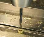 |
Install the drill chuck, bring the table over to the zero on the x-axis,
and drill the #11 bolt clearance hole. |
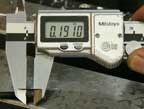 |
Measure the depth of the bolt
head, so you'll know how deep to
countersink the bolt into the brass rod. |
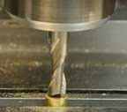 |
Install the 5/16" diameter
end mill in a collet, bring the table over to zero on the X-axis, and
lower the quill until the end mill just touches the surface of the brass. |
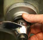 |
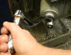
Set zero on the Z-axis dial. |
 |
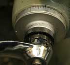
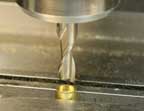
With the mill running, slowly
crank the knee upward until you reach the measurement you made of the
countersink depth. |
 |
In this case, it's .191" |
 |
You should have a nice looking,
centered and countersunk bolt hole. |
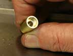 |
Here's the finished brass handle. |
 |
The only thing left now is
assembly. Make sure you've cleaned off
any burs or rough edges from all that milling and drilling, and stick
the two button head cap screws through the clearance holes in the arm. |
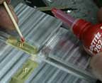 |
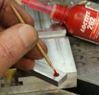
To avoid seizing the pieces
together, you need to be careful with the application of thread locking
compound. Use a toothpick to apply
a small drop inside the threads of the brass sliders, and screw the button
head screws in place. Bring them up fairly tight, and then back them off
until the sliders just move freely without being really loose and sloppy. |
 |
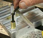
Same for the swivel handle. A
small drop of thread locking compound on the inside threads only. Adding
extra compound to the external thread of the screw may seem like a good
idea, but there's always the possibility that it will leak out between
the brass and aluminum parts, so try to avoid that temptation. |
 |
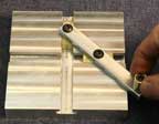
Screw down the bolt, back it
off until the handle rotates freely. Now, avoid the temptation to operate
the slider for while so the thread locker can do its job, which is to
make sure the bolts don't loosen or tighten when the handle is cranked. |
 |
Congratulations. Now you have a cute little gizmo with virtually
no practical use. But it's fun to show off. . . |


